The project was to build a “single axis” drawing machine in one night. This machine uses two independently controlled carriages on a single piece of MakerSlide rail to control a pen at the tip of two linkages. The primary purpose of the project was a fun group build and a learning exercise in setting up a non-Cartesian machine using inverse kinematics. Kinematics in this case means mathematically describing the machine to the CAM controller. The One Axis DrawBot is a very simple non Cartesian machine.

The equations used are shown above. The ends of the linkages on the carriages end are at joint[0] and joint[1]. The pen is at pos->tran.x and pos->tran.y. The first two equations convert the desired pen location back to actual machine locations. They were plugged into the CAM program. The last two equations do the opposite and convert machine locations to the pen location.
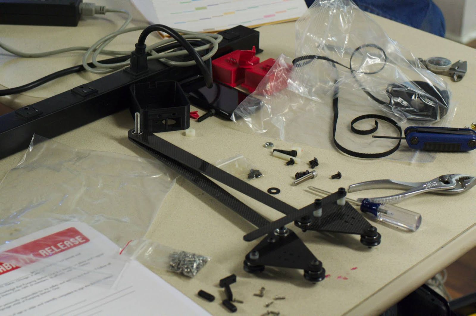
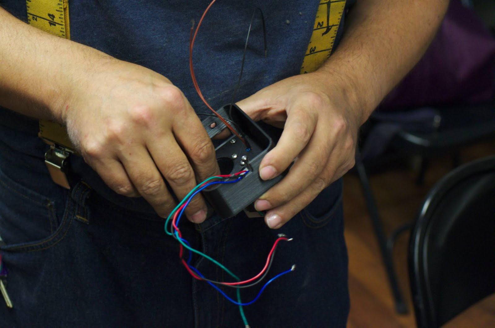
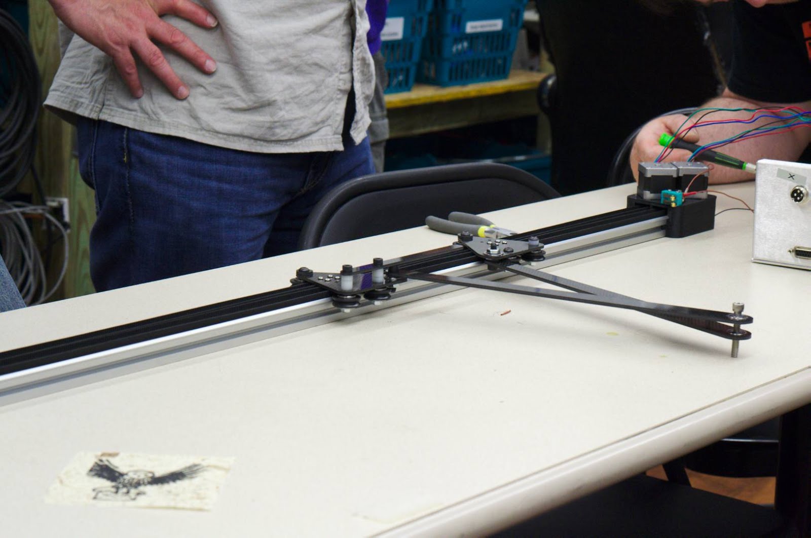
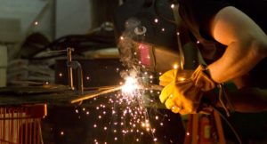
We had one team assemble the machine, one team wire the electronics and one team setup the controller. It took about two hours to complete that phase. We try to use newbies wherever possible, so adding solder training into the mix usually adds a little time. The next step was to setup the CAM controller.
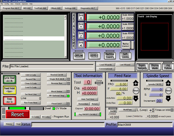
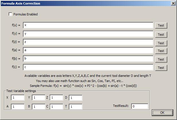
We borrowed the CNC router computer and control box to run the machine. This has Mach3 CAM controller software on it. Mach3 has a “formulas” feature that we used to enter the kinematics. We quickly had the machine running, but it was soon clear that Mach3 was not completely up to the task. In the formulas mode, it appears to disable the DROs (digital read outs) which tell you exactly where the machine is. It was also difficult to home or tell the machine the current location. Moves in the Y axis are non linear and need to know the current location. This resulted in Y axis moves that were not 100% accurate.
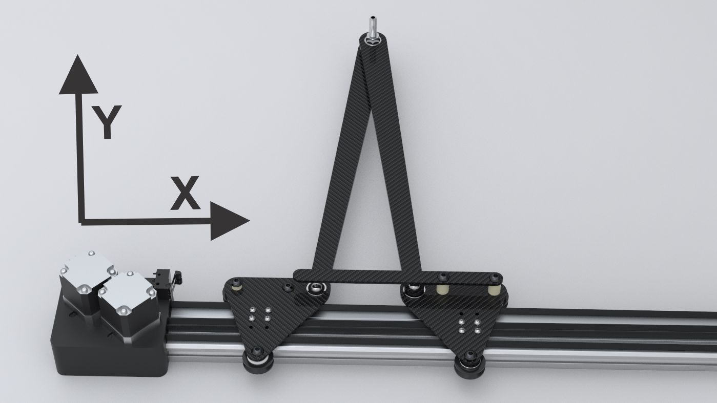
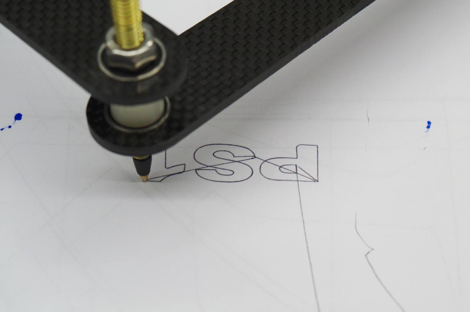
The other problem was coordination. If you tell a CNC machine to move from X0, Y0 to X1, Y0, it accelerates up to the desired speed then decelerates to the end point. If you tell it to move from X0,Y0 to X1 Y10, the two axes are moving different distances, so it needs to coordinate the different axes speeds and accelerations. The X axis would move quite a bit slower to coordinate with the longer Y distance to get a straight line. Mach3 was coordinating the two machine axes, but it was not coordinating the pen axes. Moves in only X or only in Y were nice and straight, but moves in both X and Y had a bit of a curve to them, but they did accurately arrive at the end point. A graphic with a lot of short moves would not show any on the problems above so we ran a quick “PS1” graphic. Watch the video and be sure to wait for the applause.
[youtube]http://www.youtube.com/watch?v=pze062nYps8[/youtube]
We will switch to using EMC2 (LinuxCNC). This has a true inverse kinematics feature that should fix the problems.
There is some discussion on the EMC user mail list to help us with this project.
Update 6/23/2013: Here is the latest (untested) version of our LinuxCNC kinematics file mykins.c